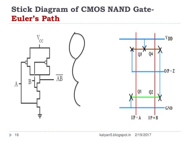


Project: 6T SRAM Cell in 0.5um SCMOS technology. Just as with component diagrams, these groupings are represented as file folders. Advanced topics: standard cells, Liberty format (.LIB).

Packages: A UML shape that allows you to put different elements into groups. For example, Psycho Killer is outside the scope of occupations in the chainsaw example found below. All use cases outside the box would be considered outside the scope of that system. System boundary boxes: A box that sets a system scope to use cases. In complex diagrams, it is important to know which actors are associated with which use cases. It is build as an easy to use scripting feature. It is a pure scripting interface without any graphical output and runs independent to the LayoutEditor application.

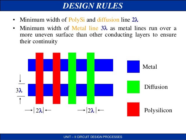
LayoutScript is available for Python and Ruby. Use cases: Horizontally shaped ovals that represent the different uses that a user might have.Īctors: Stick figures that represent the people actually employing the use cases.Īssociations: A line between actors and use cases. LayoutScript in an alternative scripting interface to the build-in C++ Macros having the same Application Programming Interface (API). To depict the system boundary, draw a box around the use case itself. Stick figures represent actors in the process, and the actor's participation in the system is modeled with a line between the actor and use case. The different layers and contacts for CMOS designs are described and this leads to a discussion of the design rules needed when laying out integrated circuits. Use cases are represented with a labeled oval shape. This tool is relatively easy to learn and use, and serves as a good tool for layout courses such as EECE479. Here are all the shapes you will be able to find in Lucidchart: UML is the modeling toolkit that you can use to build your diagrams.
#LAYOUTEDITOR STICK DIAGRAM HOW TO#
You can use this guide to learn how to draw a use case diagram if you need a refresher.
#LAYOUTEDITOR STICK DIAGRAM MAC#
On Mac it had to be installed manual.The notation for a use case diagram is pretty straightforward and doesn't involve as many types of symbols as other UML diagrams. Some packages includes it (Windows), on Linux it is marked as dependend packages, so it should be installed automatic. The entries for it will only be visible, if the tool is found on your system. In many cases, diagrams will feel like they make themselves as. To start, choose from one of the many included diagram templates (there are literally thousands) and SmartDraw will walk you through the rest with intuitive tools and lots of included symbols at your fingertips. For 3d Boolean Operations the external Tool OpenSCAD is used. SmartDraw is the easiest and most powerful diagram maker on the market. Basic editing feature are in the Draw menu and also available in the context menu. The editing work also very similar to the 2d design. Both can be set independed to the 2d layout. So hierachical designs can be used in the same way as in the 2d layout.Īlso the concept of userunits and database units is identical to the 2d layout. Meshes for volumes/surfaces, always belonging to a layer,.There are two types of entries for a design: The slect statistic in show in the lower right. Selecting is done by pressing the left mouse key. A context menu is available by pressing the right mouse key. A rotation of the view is done a holding the left mouse key. With press and hold the right mouse key the design can be moved. The user interface is similar to the user interface of the normal 2d layout of the LayoutEditor: There is a main drawing area in the middle. Opening the 3d window will always show the 3d dock window inside the main LayoutEdiotr window to generate 3d designs from a 2d layout. Alternative you can start the 3d editor by starting the LayoutEditor with the command line option -3dedit. To open the 3d window press the corresponding button in the Dialog toolbar. The 3d editor is integrated into the LayoutEditor. The 3D model/3D view can be exported and used for example for a FEM-analyse. The graphical setup can be done in few seconds. The LayoutEditor allows a fast three dimensional visualization for your design. A two dimensional designing can sometimes be quite abstract.


 0 kommentar(er)
